| Home | IONOTRONICS | Blog | Purchasing | Contact |
 Videos on the Networked Robots Platform
White Paper on Networked Robots by IONOTRONICS®
 . . |
Full paper on Networked Robots available on viXra.org. Check here |
 |
|
(c) 2012-2023 IONOTRONICS Corporation, All Rights Reserved
For the Microraptor® see here. For using a Magnetometer to measure Robotic Rover (Microraptor®) Orientation see here. Included are Youtube Videos of Tri-Track Rover Tanking and Orientation displayed on Java Compass Bean as it rotates.
Introduction
The IONOTRONICS Architecture for Networked Robots is designed so that entities at the Enterprise such as a Java Application can access multiple Robots with real-time on-demand reading of sensors and the control over Robot motion. If an application can simultaneously have access to the sensors of multiple Robots then sophisticated algorithms can be developed to coordinate the movement of multiple robots. The combined full knowledge of all aspects of the Robot, sensors and motion control, open up the capability to make multiple Robots act in a coordinated and purposeful way. Contrast this situation to where only a single Robot is controlled by a single application. Also using networked robots is significantly different for cases where multiple robots are autonomous with preprogrammed motion and reaction to sensors (think of swarms).
In this white paper we will describe how this is achieved. Note that we also present multiple videos showing the Networked Robots Architecture in action. A significant aspect of this architecture is that multiple independent entities can access the Robot through a real time connection. For example, while a Java Application is monitoring and controlling a Robot, another entity such as an HTML5 Websocket Client can also control and monitor the Robot through a Web Browser.
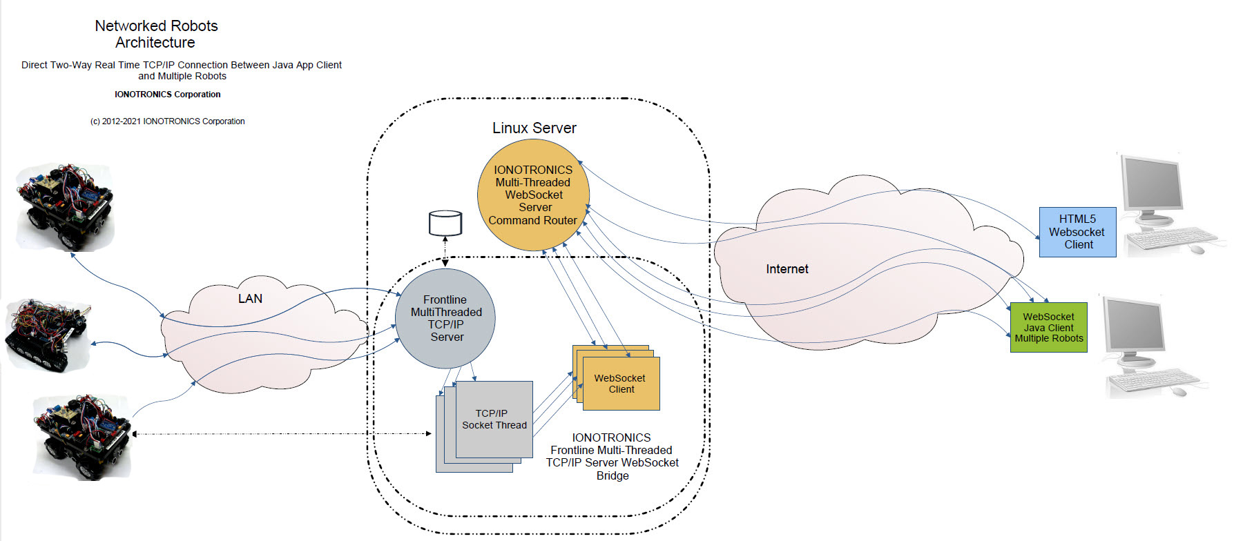 Figure 1 Networked Robots Architecture
Theory of Operation
In the Architecture Diagram, Figure 1, the "Frontline" Server written in Java is responsible for connecting to the Robot. Each Robot is equipped with a WiFi module. The WiFi Module has a multi threaded server listening to a port. When a connection is made from the Frontline server to the WiFi Module, a TCP/IP socket connection is established. Any data sent by the Frontline Server will appear at the UART ( Rx) of the WiFi Module. Likewise any data sent by the Robot to the WiFi's UART (Tx) will be received by the Frontline Server.
Frontline Server
The Frontline Server is multi-threaded and, once a TCP/IP connection is established with a Robot ( through the WiFi Module), a new thread is created to handle the connection. The thread also establishes a connection to the Websocket Router Server.
The key to the operation of the Networked Robots is the "unique id" associated with each Robot. Each Robot has an entry in a Table in the Robotics Database ( in this case using MySQL). The Table has multiple columns including three key columns (fields): The unique_id, the IP address and port of the WiFi module. Note that each WiFi Module is configured with an IP address and Port.
Once a connection to a Robot is established by the Frontline Server, the Server sends heart beats to the Robot on a periodic basis. In this case it send "xx" to the Robot. The Heart Beat is very important in that it helps maintain the connection and also is used by the Robot to determine if the link is alive. It is also used by the Robot to do a Hard Stop if the link is lost as described in the sections below.
Websocket Router Server
When the Frontline Server is started, it makes a connection to the Database Table ( Robots) and for each row, the unique_id is obtained and the associated WiFi Module IP/Port is also obtained. The Frontline Server starts a thread and makes a connection to the WiFi Module of the Robot. The unique_id associated with the Robot is provided to the thread. The thread then makes a connection to the Websocket Routing Server and provides the Websocket Routing Server with the unique_id. In this fashion, any enterprise or remote entity can provide the unique_id of the the Robot upon establishing a connection to the Websocket Router Server. The Server then routes any data form the entity to the Robot through the thread established by the Frontline Server. Thus, a direct two way real time connection is established between the entity and the Robot.
Robots
Robots can be mobile or fixed. Robots have a WiFi Module and an System on a Chip (SoC) and multiple sensors as well as motors for motion in the case of mobile devices or joints in a Robotic Arm. For the purposes of this white paper, we shall consider a Mobile Rover, the IONOTRONICS® Microraptor®. The Microraptor® is shown in Figure 2. In this case the SoC is a Microchip PIC32MX360F512 32 bit MIPS based processor.
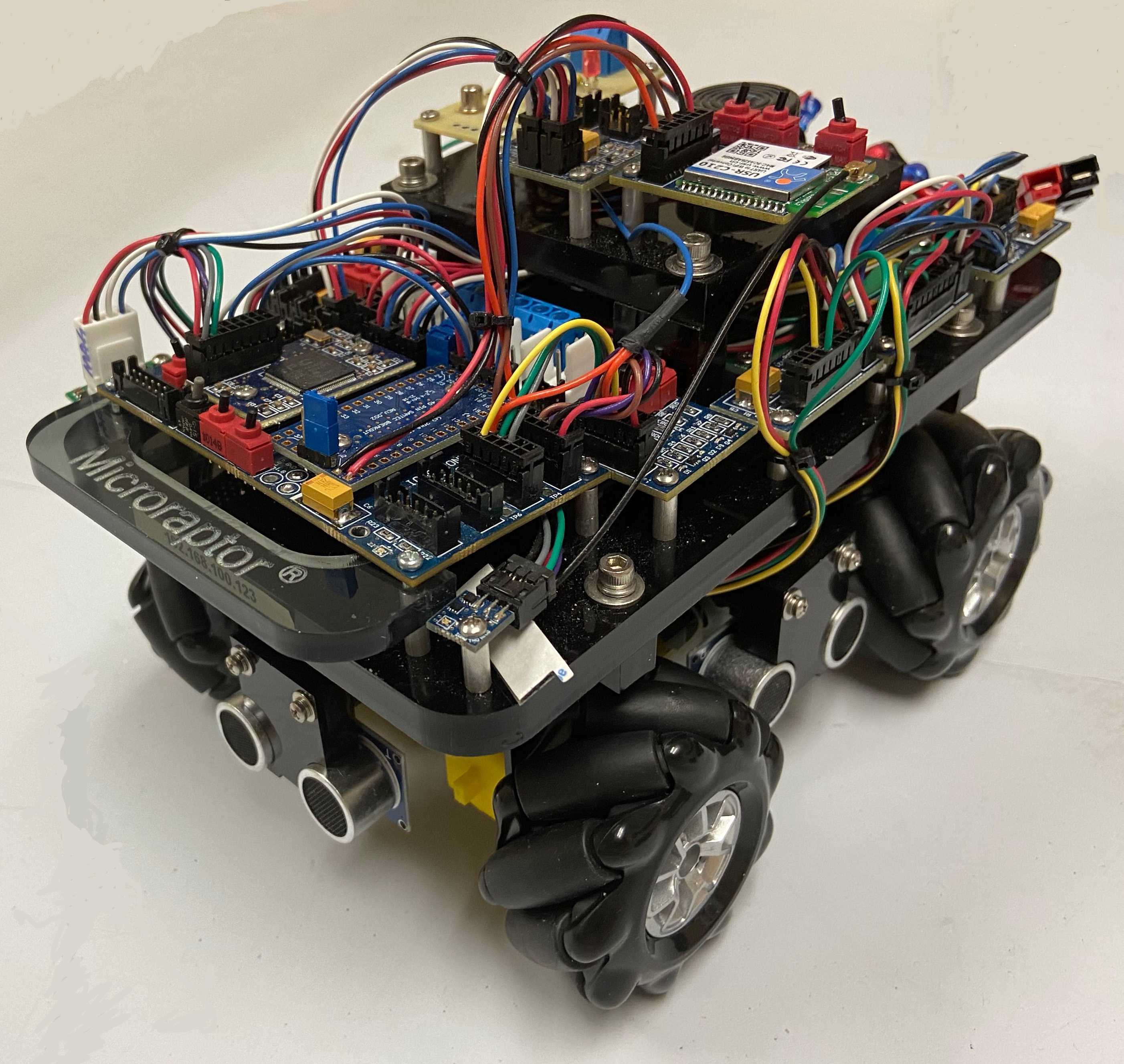
Figure 2 Microraptor® Rover
The Microraptor® WiFi Unit and Sensors are shown in Figure 3.
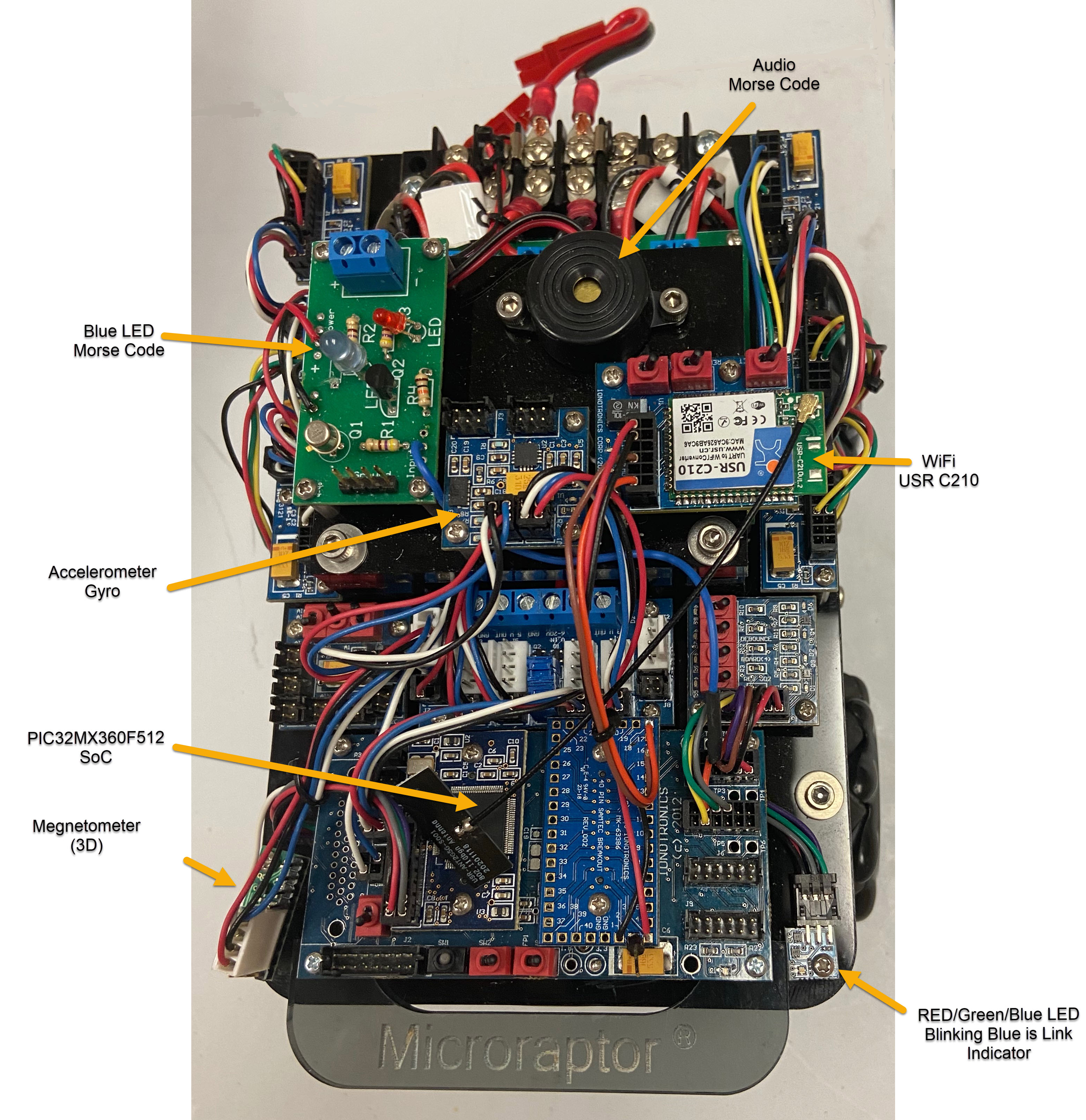
Figure 3 Microraptor® WiFi Module and Sensors
The Microraptor® is Omnidirectional ( with four Mecanum Wheels) and thus has four independent PWM Motor Controllers (on an I2C Bus). It can move Forward/Reverse, Tank (CW/CCW) and Lateral as well as Diagonally.
The Microraptor® has four Ultrasonic Sensors on each side ( since it is Omnidirectional). This way we can detect obstacles in each direction. The Ultrasonic Sensors are made available to the I2C Bus with the SoC as I2C Master using a PIC16F1825 per Ultrasonic Sensor.
Link Blue LED Indicator and Hard Stop Red LED Indicator
When a link is established with the Rover, the Blue LED of the RGB LED will blink at a fixed time interval. The Firmware running on the Microraptor® is called the Remote Robot Control Program (RRCP). The RRCP includes a timer that causes an interrupt on a specified time interval. The Rover receives a code ("xx") from the Frontline Server on an interval basis. If this code is received, a global flag is set. In the Interrupt Service Routine of the Timer, if this global flag is set, then the RGB LED Blue is toggled. If it is not set, then the Rover is Hard Stopped. This indicates that the Rover is out of range or the link has been disrupted. So a blinking Blue LED shows an established and maintained link. A red LED indicates loss of link. If the link is re-established the Blue LED will flash. No need to reboot the Robot. To see all this in action see this ![]() .
.
Robotics Database Table for Robots
A screen shot from the Linux Workstation of the Robots Table ( Using mySQL Workbench) is shown in Figure 4. The Unique ID for each Robot is the Hexadecimal Representation with ":" between 8 bit values ( a 48 bit code). As can been seen in the table, associated with each unique ID is the IP address of the WiFi Unit. The Port used in the WiFi Unit is also shown. The Robot table has a field for the type of Robot as well as type of Motor and a description along with other fields.
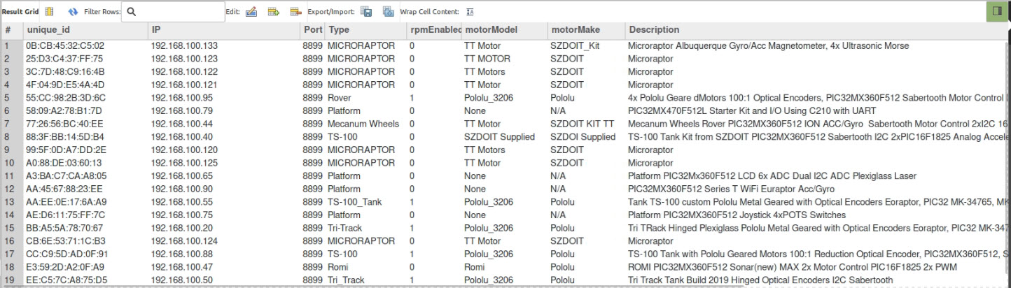
Figure 4 Robots Table in the Robotics Database
In the case where the type is Platform, this usually refers to fixed location Robots, such as a Robotic Arm. Robotic Arms are also controlled with the RRCP Firmware. In our case, each joint is controlled by a PIC15F1825 chip, generating a PWM signal, with an I2C address. The SoC is the I2C Master.
Control of Robots Using an HTML5 Websocket Client on a Chrome Web Browser
Using an HTML5 Client with Javascript, a Websocket connection can be made to the Websocket Routing Server. In this case the unique_id of the Robot is provided to the Websocket Routing Server and a direct two-way real-time connection is established from a Web Browser (Chrome in this case or Brave) to the Robot.
A video ![]() shows the control of multiple Robots using an HTML5 client through a Web Browser.
shows the control of multiple Robots using an HTML5 client through a Web Browser.
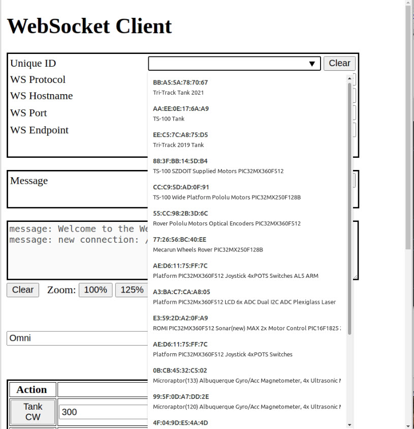
Figure 5 Zoom In on the Robot List Pulldown Menu in the HTML5 Client
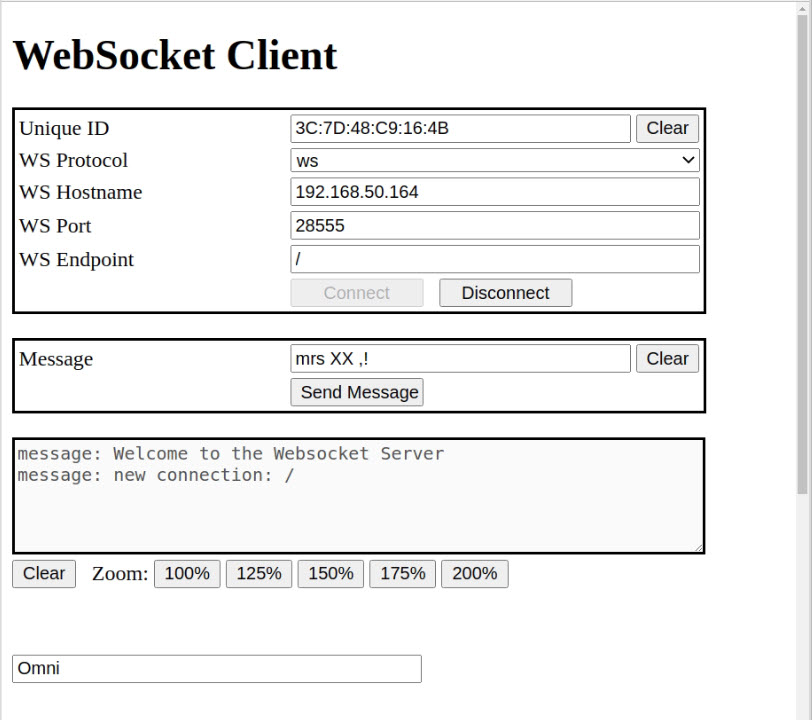
Figure 6 HTML5 Websocket Client Showing Connection to a Robot ( Unique ID ).
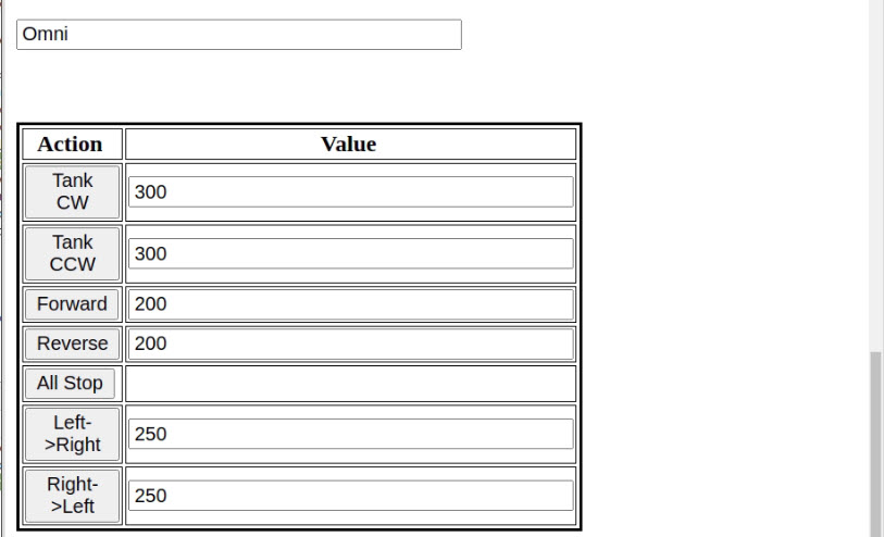
Figure 7 HTML5 Websocket Client Zoom In on Motion Control
In the Figure below, multiple Microraptor® Rovers are on the Networked Robots Platform. See the video ![]() . In this
. In this ![]() three Microraptor Rover Robots are simultaneously controlled by a signal Java Application through the Websocket Router Server and Frontline Server.
three Microraptor Rover Robots are simultaneously controlled by a signal Java Application through the Websocket Router Server and Frontline Server.
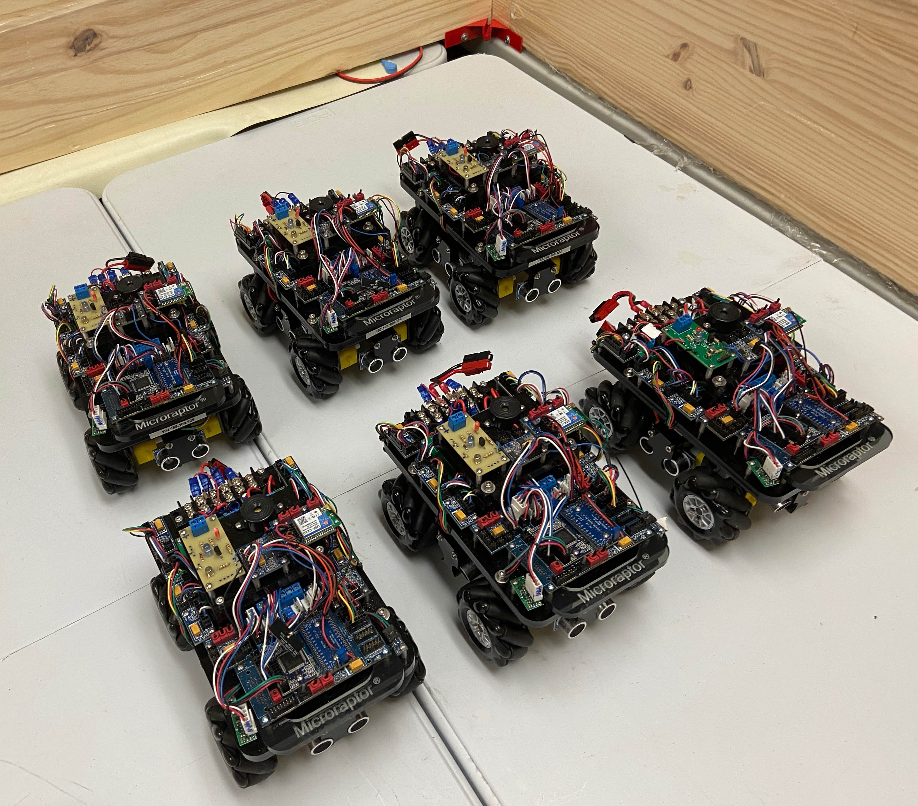
Figure 8 Networked Microraptor® Rovers