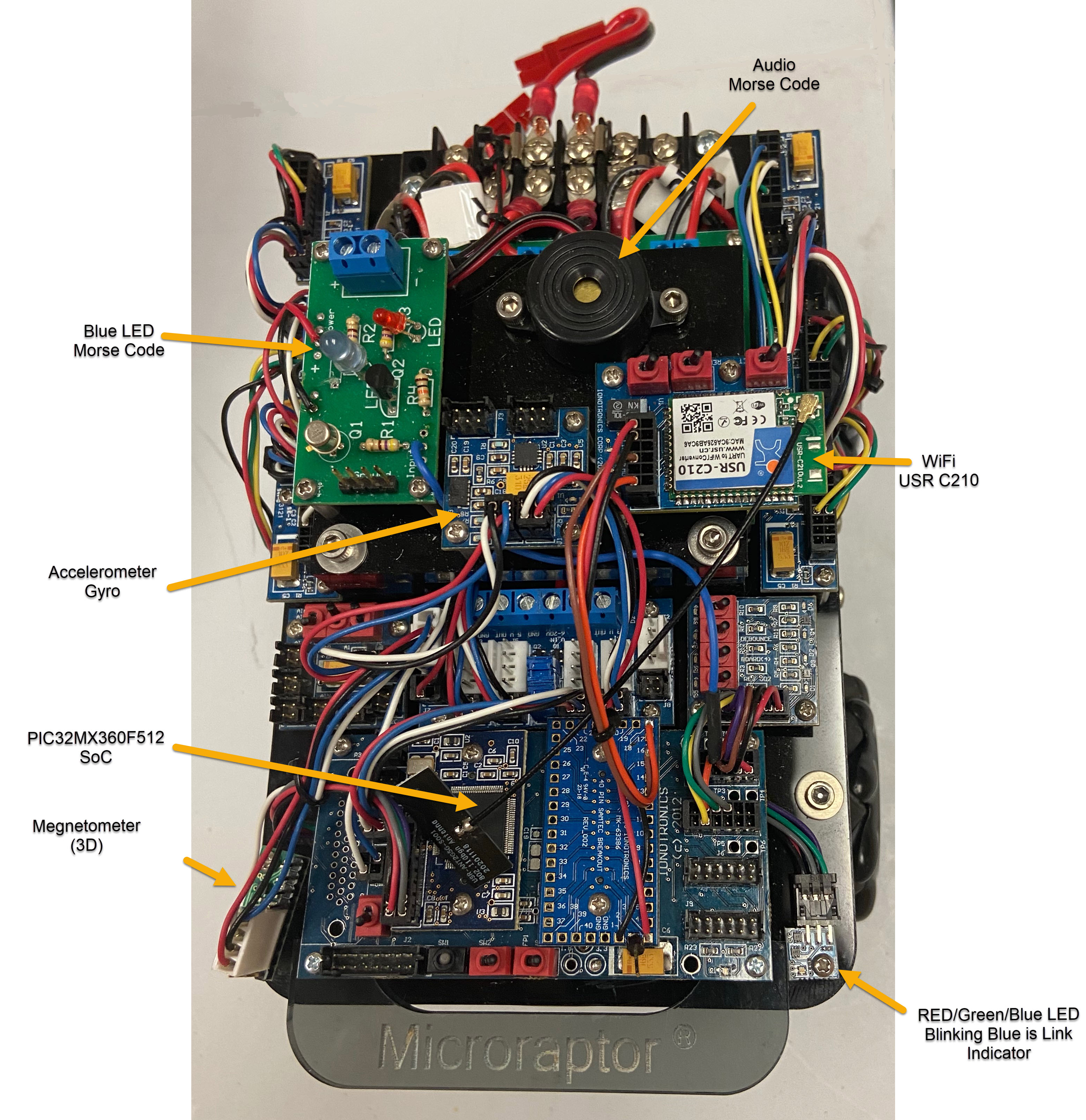
In this paper, we will show how to measure the Robot orientation using a 3-Axis Magnetometer. We will be using the ST Micro LIS3MDL. In particular, the Pololu 2737 Carrier. In the photo below the Microraptor® is shown with the Magnetometer mounted at the top. In the development below, we are interested in the X and Y axis and cases where the Microraptor® is level with no pitch or roll. An excellent reference on Magnetometers is the following link which also uses the LIS3MDL.
How to Calibrate a Magnetometer By Shawn Hymel (Digikey).
Also checkout the links provided by Shawn, in particular:
Magnetometer Hard & Soft Iron Calibration
Here is the photo of the Magnetometer mounted on the Microraptor®.
It is important to emphasize that we are interested in orientation about a known direction ( all horizontal plane).
Here are the important steps:
1- Measure Raw X,Y,Z from Magnetometer as Microraptor is rotated.
In this case we measure the Raw X,Y and Z axis from reading the Magnetometer (interfaced to I2C Bus). We do this by making measurements on an interval basis and storing the measurements in a file as we rotate the Microraptor® multiple times covering multiple angles. See the raw data here.
Here is a partial result from the file:

2- Using the X Axis measurement calculate the maximum and the minimum value (XMAX and XMIN).
3- Calculate XHI=(XMAX+XMIN)/2.
4- Using the Y Axis measurement calculate the maximum and the minimum value (YMAX and YMIN).
5- Calculate YHI=(YMAX+YMIN)/2.
6- Here are the results:

7- For each raw X calculate xc=X-XHI.
8- For each raw Y calculate yc=Y-YHI.
9- Compute theta=atan2(xc,yc)*180/PI
9- If theta <0 add 360.
11- We now have the orientation theta.
12- So for a particular Microraptor® we compute XHI and YHI. Then for measuring the orientation, we subtract XHI from X and YHI from Y, compute theta as above and this is the orientation.
For the measured raw data, the plot below shows the calibrated xc and yc:

The calibrated angle (theta ) is plotted below. Note it tracks the Microraptor® being rotated and also shows the range of theta (-180 to 180).

See the Video ![]() for a great demonstration of measuring the Orientation of a Microraptor® via the Internet using a Java Application (which obtains the calibrated orientation from calibrated parameters for the particular Microraptor®) using Networked Robots. For the Tri-Track Robot Tanking and Bench Test see:
for a great demonstration of measuring the Orientation of a Microraptor® via the Internet using a Java Application (which obtains the calibrated orientation from calibrated parameters for the particular Microraptor®) using Networked Robots. For the Tri-Track Robot Tanking and Bench Test see: ![]() and
and ![]() .
.
